
When we use these values, Vout of our voltage divider will be around 3V.

For Z2, I have chosen a resistor value of 47K and if we calculate Z1, based on that value it should be 17K, however the usual resistor assortment does not include this value. Another consideration is more of a practical nature and that is the readily available resistor values. The impedance of the analog pin A0 is very high and draws around 10 ♚ (microAmpere) of current, so we can ignore it in our calculations. The conclusion is that the bigger the resistance of Z1 and Z2 is, the less current we will draw. The formula to calculate the current through a voltage divider is: The other consideration is the power consumption as we know P = V * I, the less current we draw the less power of the battery we will consume. The resistance of Z1 needs te be smaller than Z2 75% smaller. The ratio is more or less 3/4 between the output and the input. So we need to choose our values that 4.2V will output 3.3V. The output Vout is calculated using this formula: The voltage divider circuit needs 2 resistors connected in series. We also need to keep in mind that the voltage divider itself also consumes battery power and we need to draw as little current as possible. So we need to create a voltage divider circuit to drop the voltage that is send to that input to the maximum of 3.3V. Our Li-Po battery is 4.2 or even sometimes 4.5 volts on full charge so if we would directly connect it to the analog port it would destroy the ESP chip on the board. The values that can be read out are between. The analog input of the WeMos module can measure voltages between 0 and 3.3V. This is easily done using a voltage divider circuit and the analog input on the WeMos D1 mini module. At this point the meter is programmed for the correct battery chemistry and cell count, so it should be accurately measuring the current state of charge (SOC).In addition to the WeMos battery powered temperature server, it would be nice to know what the remaining level of the battery is, so we can recharge it in time. When you have chosen the correct preset, press the O button to return to main screen. You can use the K+ and K- to scroll through the available menu options.

The display will show the current battery preset that is selected. With the meter powered off, press and hold the K+ on the back and power on the meter. Please refer to the knockout reference table below. In most installations, you will need to knock out an additional 1mm on each side for the tabs to fit in the knockout. The meter will require a rectangular knockout to insert and is held in place by pressure-fitting tabs on each side. Make sure to pay attention to the orientation of the plug before inserting. The back of the display has a B- (Battery Negative) and B+ (Battery Positive) marking indicating the correct polarity for installation. Next, you will need to insert the 2 pin plug on the pigtail into the rear of the meter. Connect the Black wire to your batteries Negative (-) terminal and connect the Red wire to your batteries Positive (+) terminal. In some cases, this length will be too short so it is suggested to splice on any additional length that you might need.

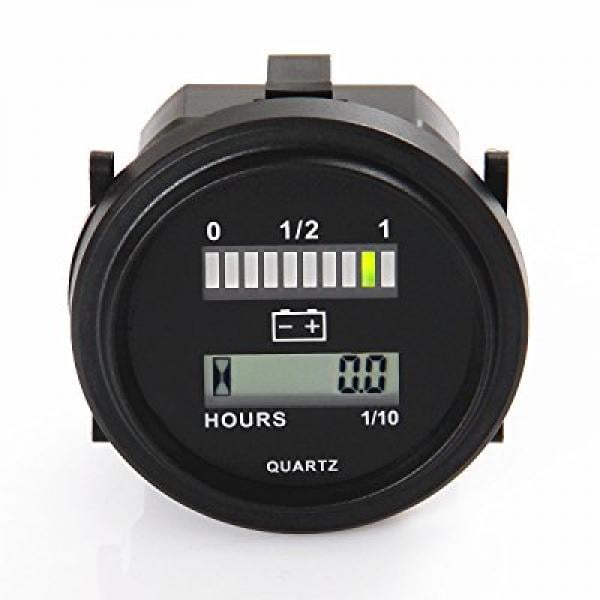
The meter is supplied with a 7in long pigtail to hook up to your battery. The BVM-100 can be easily programmed on the go and does not require any Rev additional tools or devices to program out in the field. This unit is compatible with most Lithium, Lead Acid, and Lithium Iron Phosphate batteries ranging from 12-60V. The meter accurately measures your batteries state of charge (SOC) and voltage. The Powerwerx BVM-100 is a battery capacity meter that acts like a fuel gauge for your battery.


 0 kommentar(er)
